This is the first part of a series of tutorials on DesignSpark PCB. The second part is here.
For the last little while I’ve been looking at some of the “free” PCB design tools out there for some open source hardware projects I’m considering. I initially tried Eagle which seems to be the standard “free” package out there because it gives you a limited functionality package for free. I turned it on once and promptly uninstalled it. Sorry, but I just couldn’t get past the user interface. It was completely foreign to me and I’ve used a lot of different packages (PADS, Orcad, Protel, PCAD, Altium Designer, etc). Eagle just felt broken from the first second I tried it, I think mainly because it is so different in ideology from the commercial offerings I’ve tried.
Second on my list is DesignSpark PCB. I tried it and it failed my 5 minute click around the tutorial test. So I sent an email to the DesignSpark people complaining about it. Martin Keenan, the project manager for DesignSpark PCB, replied and gave me some valid reasons to look at it again. So I figured I would but that I would lower my expectations the second time around.
My goal for this evaluation is to determine if DesignSpark PCB will slow me down considerably when doing designs compared to commercial packages. I’m really trying to embrace the open hardware philosophy, but if it takes twice as long with free tools I’ve got better things to do. My first project is going to be very simple. A PCB to adapt a modern telcom relay to replace an old Tektronix relay in my Tektronix 7A13 differential amplifier.
The first thing I noticed from the example project is that the default schematic libraries are ugly. I really mean ugly. It’s not a big deal to me since I usually create my own libraries from scratch, but I was kind of horrified. In fact, the schematic library symbols where the first thing I made me think twice for my initial evaluation. No one should be using square boxes anymore for resistor symbols! So for me library editing/symbol creation was going to be my first thing to look at.
I opened the library creation tutorial and I didn’t feel so bad. It kind of reminded me of PCAD, and I like PCAD. Simple but functional. So I made the relay symbol on the right. The one on the left is from the default Omron library.
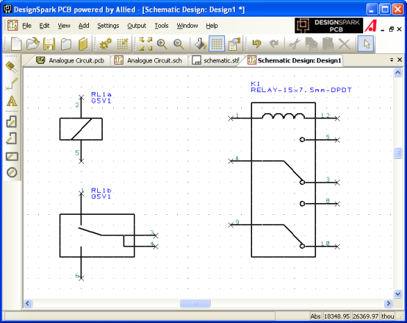
The Omron symbol isn’t too bad actually, but I’m more used to the symbol I drew. Somehow I managed to crash Designspark the first time I tried to make this example.
The next step for me was a nice schematic title block. Lots of open source schematics look really bad because they’re missing nice title blocks. I was not prepared for the what came next. I figured that everyone would want title blocks. I can make one in Alitum Designer in less than a minute. Ten if I want a fancy one. This is not the case with DesignSpark.
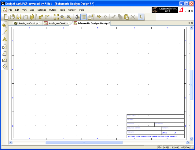
The first thing I wanted to do was set the page size. I like to draw everything in 11×17 format because it’s still legible on 8.5×11. You can’t set the page size in DesignSpark PCB. You seriously can’t. I googled and read the help files to no avail. I couldn’t believe it. And the drawing area is so big at 40+inches square that you have no hope of printing it. So I figured maybe I can scale it or select a print area. No on both counts. Luckily I found a solution by accident because this is a critical feature for me. If you print to a PDF file you get the smallest rectangle that fits all the objects in the screen. You can then print the PDF to a printer properly. Not pretty but acceptable since I don’t print often and there would be a frame around my whole schematic area anyway.
The next step was to make the nice title block in a template so that I could reuse it easily. I did some more reading and “Schematic Technology Files” seemed like they were the answer. It even says in the help file “Use the Add Shape and Add Text options to create a drawing blank with your company details in. All design level shapes and text will be saved to the technology.” Just what I wanted, except that it doesn’t work. I spent a long time drawing the template I wanted and saved it. When I tried to use it, the new schematic drawing canvas was blank. So I tried with just a text string in a new file. Still didn’t work. So I opened the example files again and clicked on the title block for Analogue Circuit.sch. It was a library component, not a drawing object in the template.
Here’s what I ended up with. It’s not the prettiest title block out there, but it will work for now.
It looks ok on the screen and is still legible when printed on 8.5×11. I’m not sure what happened, but it didn’t print out exactly as shown on the screen. Some of the text was moved slightly and the horizontal numbers weren’t lined up anymore. I’ll have to look into it more later, but for now DesignSpark PCB is looking like a good candidate for my open source hardware projects. Hopefully these hints will save you some time should you choose to try DesignSpark PCB for yourself. Stay turned for the next step where I try to actually draw a schematic!