A friend stopped by this weekend and dropped off some fun toys.

He needs a frequency locked 1000W 2.45GHz signal based on a microwave magnetron. I like the magnetron solution because it’s a cheap way to generate such a high power RF signal but they wander between 2.42GHz and 2.48GHz which is a problem for his application. I have volunteered to help him figure out a method to lock the output frequency. I think it will make a great writeup for the blog since I expect it will take a significant amount of reverse engineering and experimentation to make it work.
I would like to point out at this time that the output from a microwave magnetron is extremely dangerous. Microwaves like to boil water and people are 75% water. All of my experiments will be done in carefully controlled conditions and have been checked with a microwave leakage detector. The microwave energy in the experiments will be dissipated using a water load and also the test setup itself, not me.
The first thing we did is setup all of the equipment for the tests. The magnetron and control circuit are from a microwave oven and all of the waveguides are recycled from old equipment. The water cooling setup is a pump and radiator from an old CPU water cooling setup. Unfortunately it takes a lot more than an old microwave for a test setup. Here’s a block diagram of the basic test setup (you might have to click on the image to see it clearly):
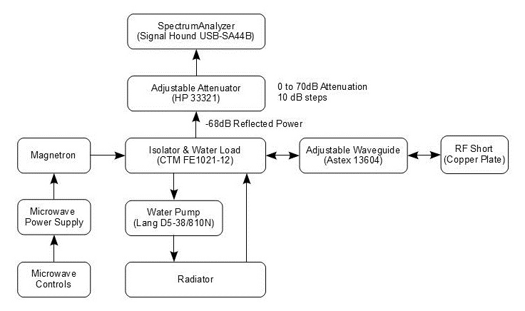
With this test setup, the magnetron can only be run for short periods of time. For example, after 20 seconds of operation the magnetron case temperature can reach 50C even with the cooling fan from the microwave blowing across it. Since the magnetron can run for many minutes inside of a microwave the test setup needs to be reviewed to see if the microwaves are being reflected back into the magnetron. Since the magnetron output is shorted, I would expect to see most of the power reflected back towards the magnetron. The isolator should be attenuating this energy by 20db or so but that means that 900W (1000W-1000W/10) would be absorbed by magnetron. Here is a good application note on how isolators work. Section 7.9 suggests a method of frequency locking a magnetron which might come in handy.
We first tried to observe the magnetron output using a Signal Hound spectrum analyzer connected to the isolator reflected power output with an external attenuator. When we tried a 50MHz span centered at 2.45GHz, the sweep rate was about 300 to 400ms. Occasional peaks were observed but it was pretty obvious that either the signal wasn’t there or it was hopping around faster than the Signal Hound could capture. Different attenuation settings didn’t help. My friend had previously tried the same test using a newer Agilent spectrum analyzer and even with a sweep rate of 50mS he observed that it was difficult to see the magnetron output. Even when the Signal Hound was set to a 5MHz span the sweep times were still 150ms to 250ms. I will have to investigate further to see if it’s possible to speed up the sample rates using either a faster PC or with different sample settings.
We also measured the input voltage to the magnetron using a Fluke 87III multimeter and a Fluke 80K-40 probe and got a DC voltage of about -2.2kV and a ripple of about 2.2kV. This surprised my friend since he thought that the magnetron was powered with a rectified DC voltage. I added a CT238 current probe and captured the following waveforms with my Tek 754D oscilloscope:

The oscilloscope attenuation factors were set so that the displayed voltage from the 80K-40 probe was approximately correct on channel 1 (the black trace). The oscilloscope was also set so that the voltage displayed from the CT238 current probe is actually in amps, ie 1V = 1A. Normally you can’t use the 80K-40 as an oscilloscope probe because it has a 3dB bandwidth of about 400Hz, but in this case the waveform is about 60Hz so it’s an acceptable approximation. The CT238 probe has a frequency response of 250kHz which is more than adequate for the signal measured here.
The peak to peak AC voltage is about 4.4kV and is shown AC coupled. The current waveform is DC coupled and is changing directions which makes sense in an AC powered system. The peak current draw is about 12A with a RMS current of about 8A. These numbers don’t make sense though because the RMS power consumed using these numbers would be 16kW (2kV * 8A) which is quite a bit more than a 110V plug can supply. I will need to try and repeat these measurements once I go over the test setup.
So far there are more questions than answers, but that’s what makes this project so interesting. After a few hours of playing here are the next steps:
- Contact Signal Hound to see if sampling can be sped up. Right now it’s too slow too see the magnetron output if it’s constantly changing frequency.
- Verify the power test configuration. The numbers measured aren’t making sense.
- Try to measure how much power is being reflected back into the magnetron. The large reflected power could cause the magnetron to change frequency rapidly.
- Can magnetrons operate on DC voltage instead of AC? Maybe a DC voltage will help stabilize the magnetron.